
First, understand the movement
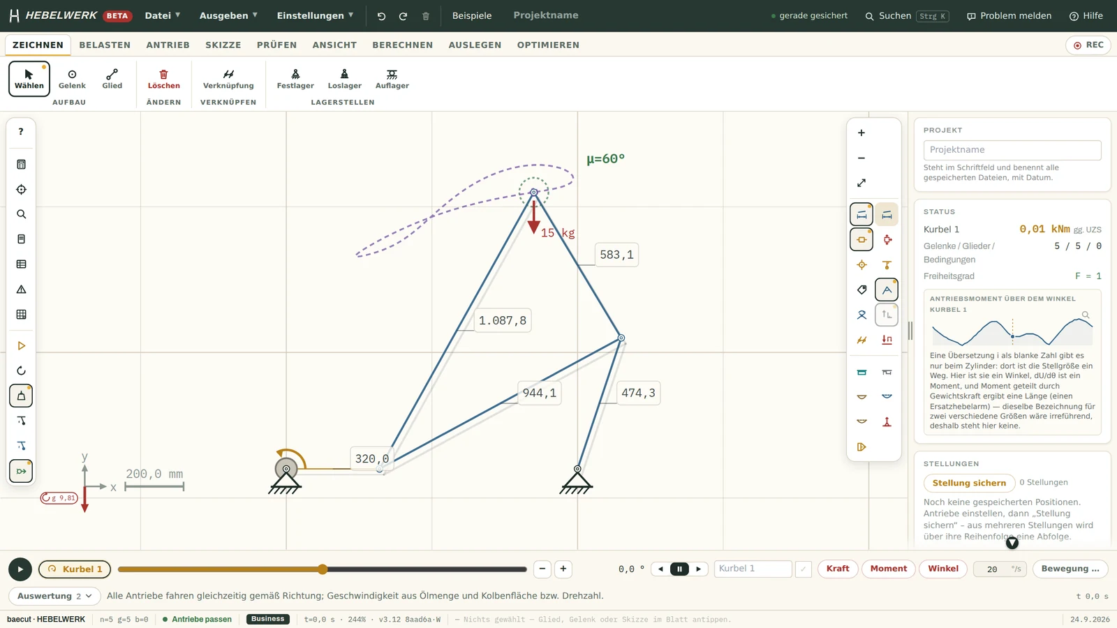
Link lengths, the coupling curve and the minimum transmission angle of 60 degrees are shown directly on the sheet. This allows you to see, before you start drawing, whether the kinematic configuration is viable.
A user-friendly kinematics editor for anyone designing boom, hoist, toggle and cylinder kinematics. Draw a model, apply loads, simulate the motion, read off the forces, carry out structural analyses and, finally, print a report showing the calculation process. All within the browser, with no installation required and without the model ever leaving your computer.
v3.12 · performs calculations in the browser · German and English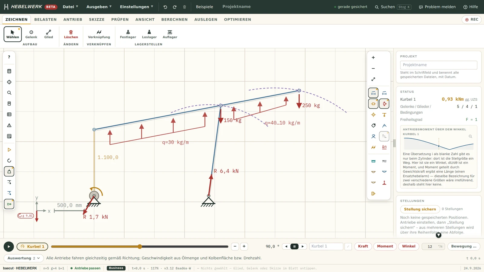
Trapezoidal load, individual loads and dead weight on a four-bar linkage with a cantilever load. Hebelwerk performs a free-body analysis and calculates the support reactions at the supports: 1.7 kN and 6.4 kN.
Link lengths, the coupling curve and the minimum transmission angle of 60 degrees are shown directly on the sheet. This allows you to see, before you start drawing, whether the kinematic configuration is viable.
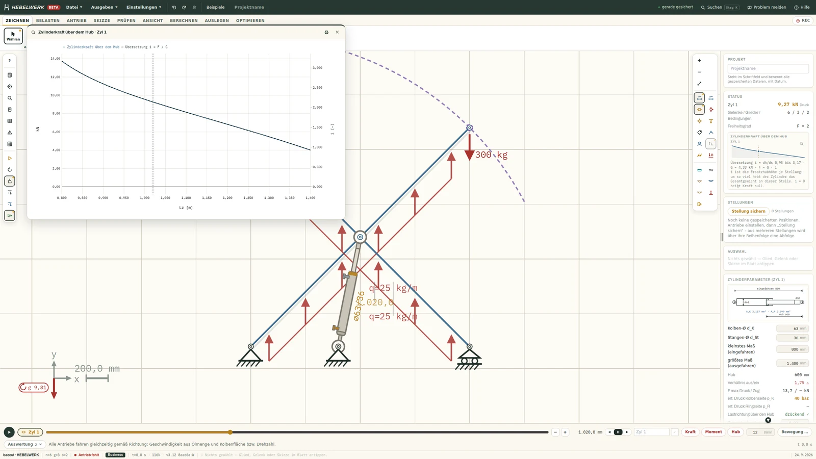
Not just a single position, but the entire path: the force per unit area over the stroke, plus the ratio i = F/G. Where the curve passes through zero, you’ll also find the reason why.
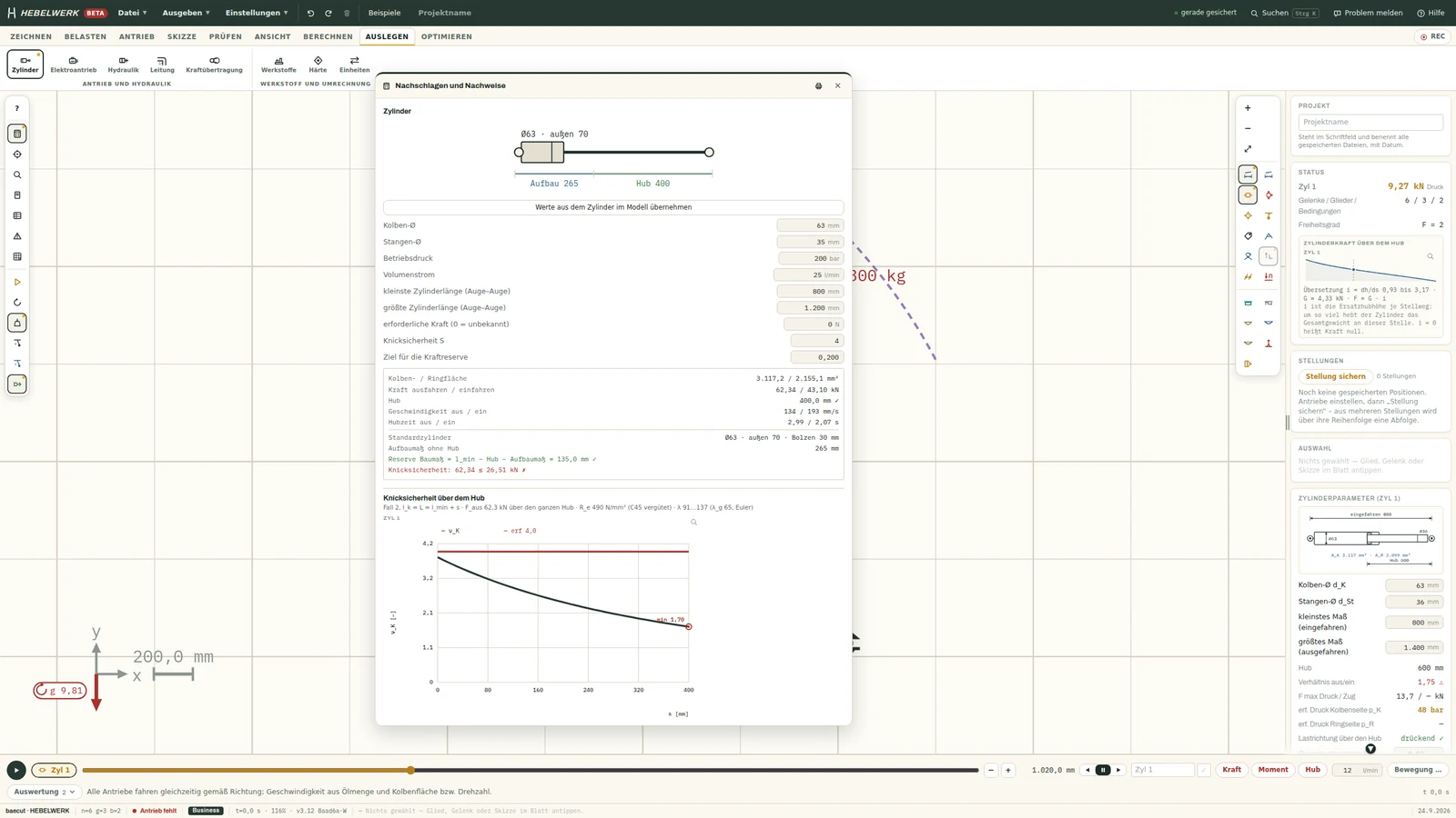
Piston rod in accordance with Euler and Tetmajer, resistant to buckling throughout the entire stroke. This isn’t sufficient here: a load of 62.34 kN against a permissible load of 26.51 kN, and that’s highlighted in red.
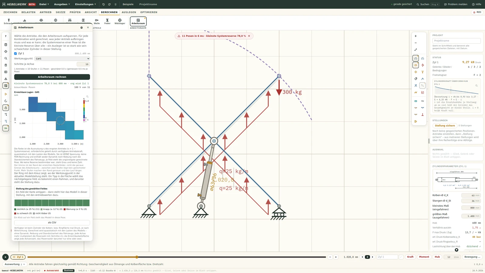
The workspace calculates each pose and colours it according to the reserve of the weakest drive. Here: eleven poses, smallest system reserve 78 per cent, all usable.
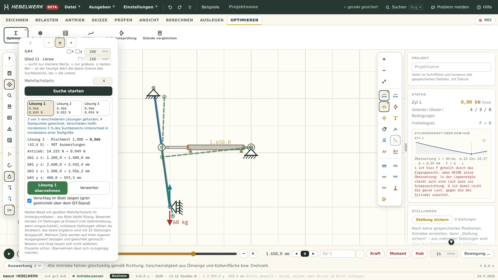
The optimiser reposition the joints within the specified search range and reduces the driving force from 14,225 N to 8,049 N. It presents three differently structured solutions, not just one.
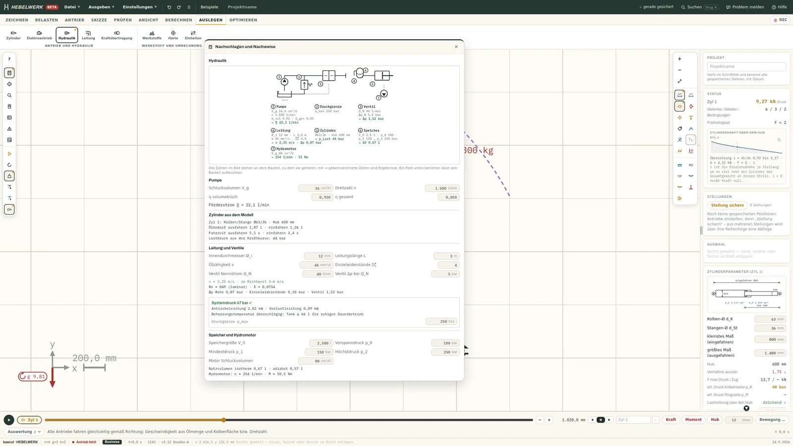
Pump, pressure limit, valve, pipe, cylinder, accumulator and hydraulic motor shown as a circuit diagram in accordance with ISO 1219, with flow rate, pressure drop and system pressure indicated for each component.
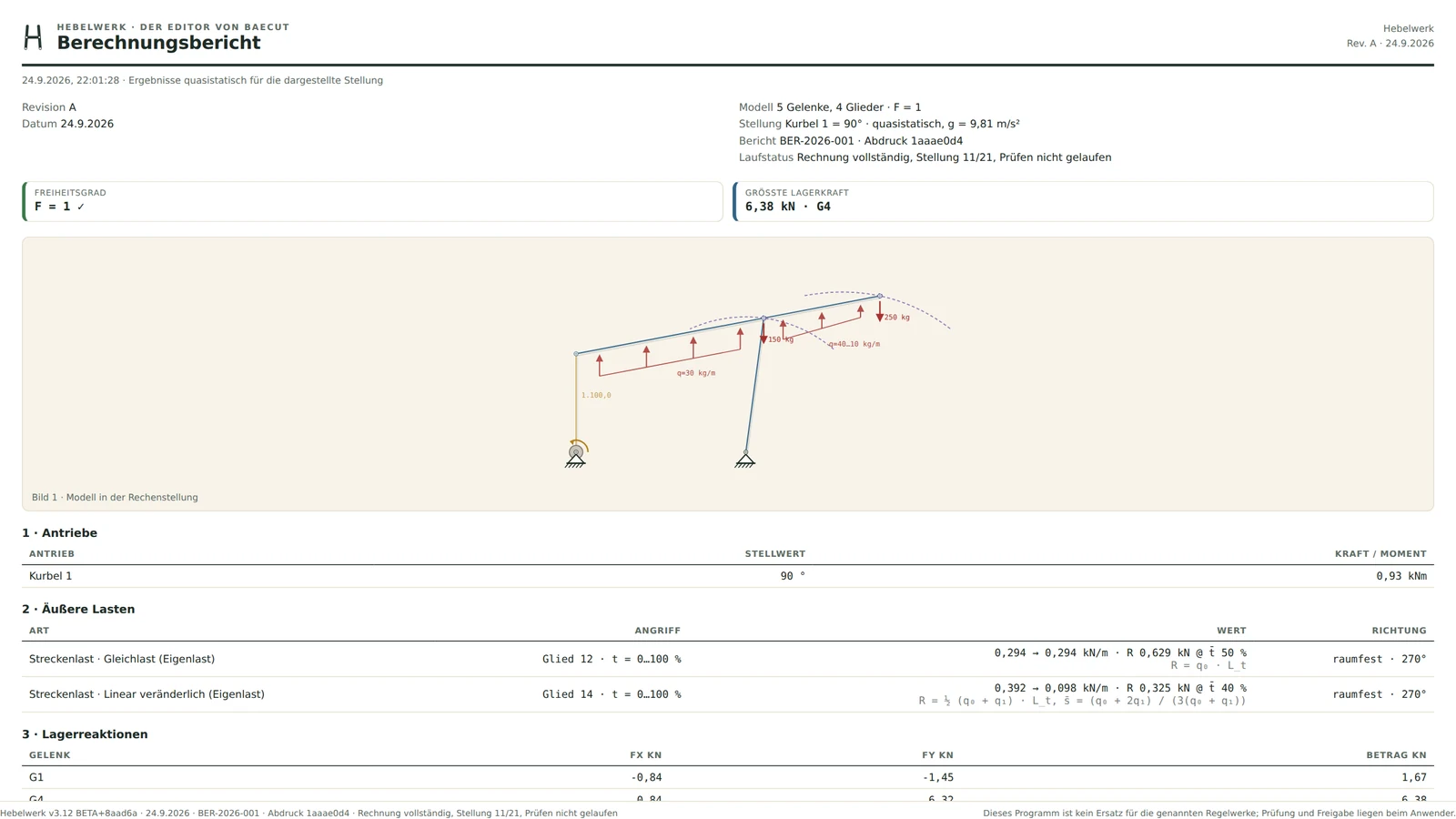
Drives, loads, bearing reactions, joint forces, assumptions and regulations on a single sheet, with an approval stamp showing the version, construction stage and a copy in the footer.
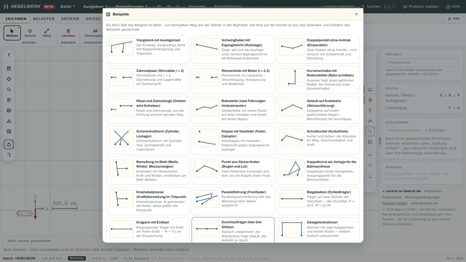
Twenty-two ready-made examples, ranging from the four-joint mechanism to the scissor lift table and the two-joint frame. One click adds one to the worksheet, after which everything can be edited.
Most solutions are worked out twice: once in the sketch and once in the table alongside it. The sketch shows the movement, but not the force. The table calculates a position, but the worst-case scenario is rarely the one you try first. Time is lost in between, and errors lurk precisely in that gap.
Hebelwerk closes the gap. The same model underpins both the motion and the calculations. Anyone who changes a dimension can immediately see how the cylinder force is affected, how the bearing forces shift, and whether the analysis still holds true.
Draw articulated tracks with multiple drives, track curves, limit positions and transmission angles on the drawing; perform a time simulation based on oil volume and piston area.
Point, line and trapezoidal loads; springs, dampers, cables. Free-body diagrams for each member or subsystem, with a table of moments and an equilibrium analysis.
Bending, deflection, bolts, sliding bushings, welded joints, screws in accordance with VDI 2230, shafts in accordance with DIN 743, springs, gear wheels, fatigue strength in accordance with FKM. Each verification specifies its limits.
Cylinders and electric actuators over the entire stroke, hydraulic circuit in accordance with ISO 1219, belts, chains, drive shafts, materials with details of origin.
The workspace colours each pose according to the capacity of the weakest actuator. The optimiser searches for better joint positions for twelve targets and provides up to three solutions.
Calculation report with text box and signature field, Excel workbook with live formulas, CSV, DXF with layers, position series, video, PNG and SVG.
The model remains on the device. Nothing is uploaded for processing, not even for the report.
The version, build status, date, report number and a screenshot of the model are shown in the footer. This makes it possible to compare two reports without having to guess which version generated them.
55 sample exercises, checked by hand or against a second source, all with figures matching the current edition. The booklet also serves as a regression reference: it is updated with every new edition.
Lever arm, angle, proportion of force, intermediate values. If you don’t believe the result, you can work it out for yourself rather than simply accepting it.
Hebelwerk It simply performs calculations and is quasi-static. It is not a finite element method (FEM); it does not replace any set of rules or approval process. Wherever an assumption is made, the programme indicates this at the point where it comes into play.
design the booms, lifting mechanisms and cylinder kinematics, switching between sketches, spreadsheets and manual calculations to do so.
for whom a large multi-body package is not suitable, either in terms of cost or effort.
The principles of gear mechanisms become clear when you pull on one link and the curve moves with it. Hebelwerk is free for university email addresses.
Calculate, verify, view. No account required, no time limit. All calculators, all verification tools, any number of members, movement and optimisation. Your design remains saved on the device, with auto-save, status checks and an undo function. Not included: printouts and files, or saving models to an account.
Zu den PreisenFor anyone who shares their documentation externally. Everything from Free, including every printout and file: reports, PDFs, CSV files, DXF files, images and videos. The models are stored in your account and accessible on any device. A seat. Thirty days’ free trial; you’ll only be charged afterwards.
Zu den PreisenFor offices that produce documents on their own letterhead. Everything from the Pro version, plus company details at the top of every page: company name, address, processor, reviewer and company logo on reports, folders and CSV files. Three seats, invoiced to the company. Thirty days’ trial period.
Zu den PreisenPro is free for students and teaching staff. It offers the same features as Pro: all printouts and files, plus models in your account. Each output bears the note ‘not for commercial use’. Company details in the header belong to the company account and are not included here.
Zu den PreisenNo. Hebelwerk runs in the browser. On Android, it can be saved as an app and will then continue to work even without an internet connection.
Exactly. Most booms and hoisting mechanisms are plane-based problems, and that’s what this tool is designed for. Collisions are also checked in terms of planes, using construction planes.
Quasi-static. Inertial forces can be applied; the time simulation is based on oil volume and rotational speed. Impact and vibration are not included.
Yes. DXF for CAD, Excel with real formulas, CSV for your own analyses, and a report as a printout.
The interface and report are available in German and English.
Hebelwerk It is constantly being expanded; each version is checked against the same test suite before release. New additions can be found under ‘What’s New’ at Hebelwerk. Errors can be reported directly from within the programme.
Open the editor, click on a tile, drag a link and see what happens to the force.
We would like to use Google Analytics to see which pages are read. This transfers data to Google, including to the USA. Nothing is loaded without your consent. You can change your decision at any time via “Cookie settings” in the footer. Privacy policy